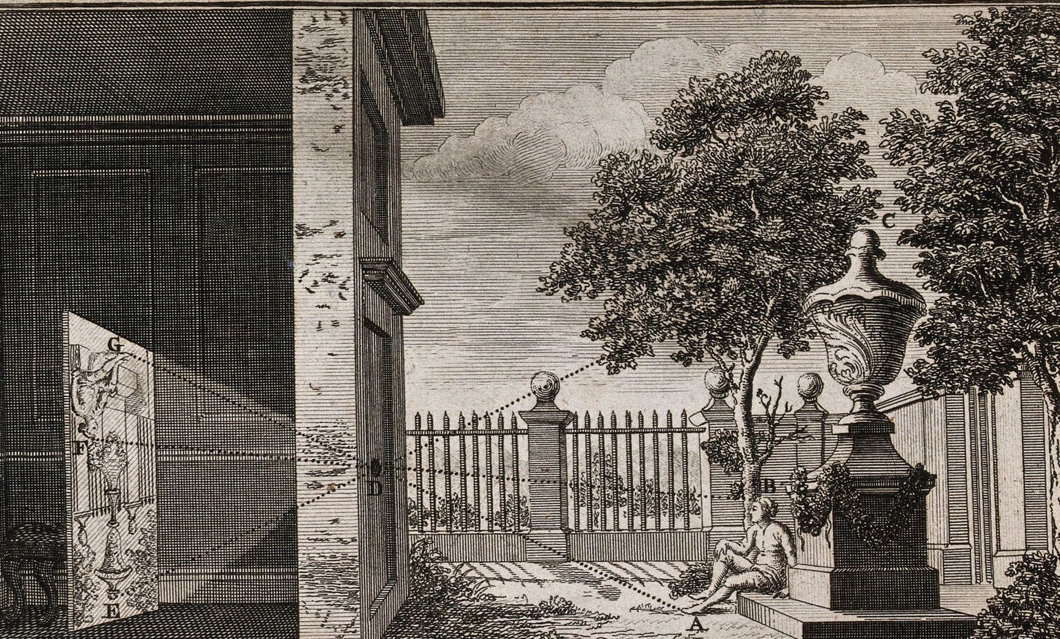
Before there were lenses, there were holes. Light from a whole sunlit garden will crowd through a gap no wider than a pin and paint the garden again, upside down, on the far wall of a dark room. People have watched it happen for more than two thousand years. How small can the hole be?
Chapter 1 · Instrument
The Pinhole
Here the instrument is nothing but a hole. Shrink it, guess what the picture does, then test your idea on the image of a single lamp.
Look first
A camera with no lens
Take the lens off a camera and put a cap with a tiny hole in its place. You have a pinhole camera. Light from each point of the scene passes through the hole and lands on the sensor as a small patch. Millions of overlapping patches make the picture. It is upside down, because light from the top of the scene travels down through the hole to the bottom of the sensor.
The subject here is a test chart called a Siemens star. Its dark wedges get narrower toward the centre. Somewhere near the middle they become too fine for the camera, and the star turns into an even grey. The size of that grey patch is a rough measure of the blur.
Look at the edges of the wedges, and at the grey heart of the star.
Photograph slot.
A Siemens star 6.4 mm across on the sensor, imaged through a 0.50 mm hole. The image is shown the right way up.
Commit to a prediction
Make the hole smaller
Same camera, same star, same green light. You start with a hole one millimetre across and halve it, again and again, down to sixty micrometres. The camera adjusts the exposure each time, so every picture comes out equally bright.
What happens to the sharpness?
The sharpest picture comes from a hole about a quarter of a millimetre across. Smaller than that, the star gets worse again. At sixty micrometres the grey heart has spread across most of the star: blurrier than with a hole eight times larger.
Under each picture is a single number: the width of the circle that holds half the light from one point of the scene. Smaller is sharper. It falls from 0.69 mm to 0.15 mm, then climbs back to 0.49 mm.
Now look closely at the 1.00 mm star, about two thirds of the way out from the centre. The spokes are there, faintly, but dark where the chart is light. A blur shaped like an evenly lit disc can do this to stripes of just the right spacing. So a grey patch is not the only sign of blur: sometimes the picture shows detail that is there, but wrong. The spreading blur of the smallest holes never reverses stripes like this. It only fades them.
Why the first guess made sense
The shadow of the hole
If you chose A, you were thinking with rays: light travels in straight lines, so each point of a distant scene casts a little bright copy of the hole onto the sensor. A one-millimetre hole makes a one-millimetre patch. Halve the hole and you halve the patch.
For large holes this is exactly right. For the one-millimetre hole, the full wave calculation and the straight-line picture agree on the blur to within two percent. Rays are not a crude approximation here. They are what waves do when the opening is large enough.
But “large enough” has a size, and it is not set by the hole alone. It depends on the wavelength of the light and on how far the sensor sits behind the hole. Below that size, light that has passed through an opening does not travel on in a straight beam. It spreads.
The mechanism
Two things pull in opposite directions
Light leaving a small opening spreads out, by an angle of roughly its wavelength divided by the width of the opening. Green light through a quarter-millimetre hole spreads by about a tenth of a degree. Across 50 millimetres to the sensor, that alone smears a point into a patch a tenth of a millimetre wide.
So the hole does two things at once. A big hole casts a big shadow of itself. A small hole spreads the light. Shrink the hole and the first blur shrinks while the second grows. Somewhere between them is a best size.
That is the plain-words story, and it is how the problem was first worked out. But it hides something. To see it, stand at the centre of the image and look back at the hole.
Light from the edge of the hole travels slightly farther to the centre of the image than light from the middle of the hole. The extra distance grows with the square of the distance from the middle. So the hole divides naturally into rings. Within the first ring, light arrives within half a wavelength of in step. Light from the next ring arrives roughly half a wavelength behind, and so on outward.
These rings are called Fresnel zones, after Augustin Fresnel, the French engineer who built the wave theory of diffraction. In this camera the first zone is a third of a millimetre across. The number of zones a hole holds tells you which picture applies. Many zones: rays work, and the patch is the shadow of the hole. A fraction of one zone: the light spreads. About one zone: light from the whole hole arrives at the centre of the image roughly together, and the patch is near its tightest.
The bench
Build the camera
Choose the hole, the depth of the camera and the colour of the light. The star is recomputed each time. The curve on the right is the blur for every hole size, with your camera marked on it.
The Siemens star through your camera
Blur against hole size, for this camera
A single distant lamp
Things to try
- Double the camera depth from 50 to 100 mm. Does the best hole double too? Read it off the curve.
- Switch to red light, then violet. Which colour allows the sharper pinhole picture, and why?
- Look at the dashed curve: the shadow blur and the spreading blur simply added together. Compare it with the solid curve near the best hole.
What you can now say
Light passing through an opening travels on in straight lines only if the opening holds many Fresnel zones. A pinhole is sharpest when it holds between half a zone and one, depending on how you judge sharpness. Smaller, and the light spreads; larger, and you see the shadow of the hole.
The size of a zone is set by the wavelength and the distance together, as √(λ f). That is why the best hole grows with the square root of the camera’s depth, not in proportion to it: a camera four times deeper wants a hole only twice as wide.
For the determined reader: the calculation, a worked case, and its limits
The quantities
| Symbol | Meaning | Unit |
|---|---|---|
| D = 2a | hole diameter (a is the radius) | mm |
| f | distance from the hole to the sensor | mm |
| λ | wavelength | mm (0.00055 mm = 550 nm) |
| N = a² / (λ f) | Fresnel number: how many zones the hole holds | none |
| r | distance on the sensor from the centre of a point’s image | mm |
The calculation
A distant point sends a plane wave onto the hole. Adding up the waves from every part of the hole at a point r on the sensor (Fresnel’s approximation, valid when the hole is small compared with f) gives the brightness, relative to the brightness with no screen at all:
I(r) = | (2π/λf) ∫0a exp(iπρ²/λf) J0(2πρr/λf) ρ dρ |²
J0 is a Bessel function: the result of adding waves around each ring of the hole. At the centre of the image, r = 0, the integral can be done exactly:
I(0) = 4 sin²(πN/2)
That is 4 when the hole holds one zone, and it is the brightest the centre can ever be: four times the light that would fall there with no screen at all.
A worked case
f = 50 mm, λ = 0.00055 mm, so λf = 0.0275 mm² and √(λf) = 0.166 mm. The blur is the diameter of the circle holding half the light from one point.
| Hole D | Zones N | Blur, full calculation | Shadow alone, D/√2 | Spreading alone | The two added |
|---|---|---|---|---|---|
| 1.00 mm | 9.09 | 0.694 | 0.707 | 0.029 | 0.737 |
| 0.50 | 2.27 | 0.303 | 0.354 | 0.059 | 0.412 |
| 0.25 | 0.57 | 0.147 | 0.177 | 0.118 | 0.294 |
| 0.12 | 0.13 | 0.248 | 0.085 | 0.245 | 0.330 |
| 0.06 | 0.03 | 0.491 | 0.042 | 0.490 | 0.533 |
At both ends the full calculation agrees with one of the simple pictures: the shadow for big holes, the spreading for small ones. Near the best hole it agrees with neither, and adding the two blurs overestimates the true blur by a factor of two. The spreading column uses the Airy pattern, which half the light falls inside when 2πar/λf = 1.680, giving a blur of 0.535 λf/a.
What changes on screen. Every length in this problem scales with √(λf). Double f and the best hole, and the best blur, grow by √2 = 1.41. Change the colour from 550 to 450 nm and both shrink by √(450/550) = 0.90. Change the hole alone and you move along the curve.
Which “best”?
Measured by the half-light circle, the best hole in this camera is 0.25 mm, holding 0.57 zones. Rayleigh, judging images by eye in 1891, preferred holes holding 0.9 zones: 0.31 mm here, which is where the familiar rule D = 1.9 √(λf) comes from. A larger hole gives a tighter core with more light thrown into faint rings around it. Which you prefer depends on the subject. Sharpness is not one number.
Where the model stops
It assumes a point far away, so the light arrives as a plane wave; an infinitely thin, perfectly opaque sheet (real foil has thickness, which darkens the corners of wide pictures); a hole small compared with its distance to the sensor; and one wavelength at a time, unless white light is chosen. It ignores the sensor’s pixels and any movement during the exposure. The scene is lit by daylight, so the patches from different points of the scene add as brightness. Within the patch from a single point, the waves add as waves. Chapter 2 asks what happens when neighbouring points are lit in step.
The dispute
Can you add two blurs?
According to Rayleigh, the first person to ask for the best pinhole was Joseph Petzval, the lens designer, in 1857. His reasoning was the plain-words story: the patch from a point is the width of the hole, plus the spreading from a small opening. Add them, find the smallest total, and you have the best hole.
In 1891 Lord Rayleigh came back to the problem. He noted that Petzval’s answer was remarkably close to his own, but he rejected the reasoning. Adding the result for very large holes to the result for very small ones, he wrote, was not admissible for the holes in between. He used instead Eugen Lommel’s complete calculation of light through a circular hole, published in 1884, and drew the pattern of light for holes of several sizes.
Then he tested it. He punched a row of holes in thin sheet zinc, from 0.021 to 0.037 of an inch, and set a paraffin lamp behind a zinc grating and behind a pair of round holes eighteen feet away. Looking through an orange-red glass at the image eight inches behind each hole, he judged the one from the 0.026-inch hole decidedly the best. Worked through, that hole held 0.9 of a zone.
That part of the record confirms the best size. Another of his observations is more telling, and the next station asks you to predict it.
A case you have not seen
One lamp, a slightly larger hole
Back to the 50 mm camera and green light. Point it at a single small lamp far away, at night, so the picture is the patch from one point and nothing else.
With the one-zone hole, 0.33 mm across, the lamp makes a tight bright spot. Now open the hole to 0.47 mm. It holds exactly two zones.
What is at the centre of the lamp’s image?
Bright centre, four times the light with no screen.
Dark centre. In light of a single wavelength, no light at all.
Stand at the centre of the image again and look back at the hole. The first zone sends its light roughly in step. The second zone sends just as much, but half a wavelength behind. Crest meets trough. At the very centre, for light of one exact wavelength, the two cancel completely. All the light that came through the hole lands in a ring around it.
If you chose A, you were using the two-blur story, the one Petzval used. Add a little shadow blur to a spot and you get a slightly wider spot. No sum of two blurs can make a hole in the middle. The zones can, because they add as waves, before anything becomes brightness. That is what Rayleigh meant by “not admissible”.
One more step. Open the hole to 0.57 mm, so it holds three zones. Before you look: the centre of the lamp’s image is
Bright again: two zones cancel, the third is left over.
Each colour has its own zones. The dark centre fills in.
The centre goes bright, dark, bright, dark as the hole opens, zone by zone. In white light each colour reaches two zones at a slightly different hole size, so the dark centre of one colour is filled by the others. You see the effect cleanly only through a filter.
Rayleigh saw it
He photographed his pair of round holes through his fifth zinc pinhole, with an exposure of eighty minutes. On the negative the two holes appeared as a pair of white spots near the centre of a black patch. On a negative, white means no light: the image of each hole had a dark centre. Rayleigh matched it to his calculated curve for two zones.
Where this explanation stops
Now put a lens in the hole
A lens bends the light from every zone so that it all arrives at the centre of the image in step. The shadow blur disappears. Only the spreading is left, set by the wavelength and the width of the opening.
A microscope objective is that idea taken as far as it goes: a lens with a very wide opening, very close to the specimen. It is tempting to finish the story here. Fine detail in a specimen would then fade gradually, as the spread patches from neighbouring points overlap more and more.
But every point of the star in this chapter was lit by daylight, independently of its neighbours. A specimen on a microscope stage is lit by one lamp through one condenser. Does the spreading still blur fine detail gradually, or does lighting the whole specimen in step change the answer?
End of chapter 1
Added to your notebook
Light travels on in straight lines only through an opening that holds many Fresnel zones. A pinhole is sharpest at around one.
What does a lens leave behind, when the specimen is lit in step?
Chapter 2 · What the Objective Caught