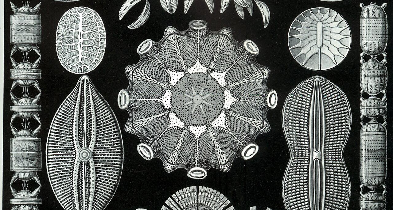
A drop of pond water holds shells of glass more intricate than any cathedral window. Under a good lens their outlines are crisp, and it is easy to believe you are seeing all of them.
Chapter 2 · Specimen and instrument
What the Objective Caught
A diatom under a good lens. What can the microscope show of its finest markings, and what changes when only the lamp moves?
Look first
A shell made of glass
This is a diatom valve: one half of the glass shell of a single-celled alga, about twenty micrometres long. A rib runs down its middle, swelling at the centre and at each end. Across its face run fine ridges called striae, like the rungs of a ladder.
The striae are half a micrometre apart: twenty in every ten micrometres, which is how diatomists count them. That is roughly the wavelength of green light, and it is the whole subject of this chapter.
Photograph slot.
What the light meets, as the model defines it. Brighter means more light gets through. This is not what any microscope would show.
Enlarge the view. Above ×1 it centres on the face of the valve, between the rib and the rim.
Commit to a prediction
Put it under a good objective
A dry 40× objective with a numerical aperture of 0.65: a good, ordinary lens, free of aberrations and perfectly focused. A green filter, 550 nanometres. The condenser below the stage closed to a pinpoint, so the light comes straight up the axis. The eyepiece magnifies as much as you like.
Across the face of the valve, what will you see?
The view above now shows the image this objective forms. Enlarge it. The outline is sharp, the rib is there, the rim is there. The striae are gone, the same at ×8 as at ×1. Enlarging spreads what the objective delivered over more of your retina. It cannot add what the objective never delivered.
At ×4 you will find faint bands on the face after all. Check their direction: they run along the rim, not across the valve. They are ringing from the rim’s sharp edge. So the face shows no detail it has, and some detail it lacks, and nothing in the picture warns you of either.
Why the first guess made sense
The blur picture, and where it holds
If you chose B, you were reasoning the way the pinhole taught. Every point of the object spreads into a small patch in the image. Bring two points close and their patches overlap; closer still, and the gap between them fills in. Detail fades.
That picture is right in its place. Helmholtz built the microscope’s theory this way in 1874, treating each point of the object as if it glowed on its own. It describes stars, the sunlit chart of chapter 1, and a fluorescent cell, where every stained molecule shines independently.
It fails here for one reason. This diatom does not glow. It is lit from below by a single narrow beam, so every point of the valve is lit in step with every other. In the pinhole, waves added as waves only within the patch from one point. Here, the light from neighbouring points adds as waves too, before anything becomes brightness.
The mechanism
Beams, and which ones get in
Ernst Abbe, working for Carl Zeiss in Jena, published the better account in 1873. A row of evenly spaced striae acts like a diffraction grating. Most of the light goes straight on, but some leaves at definite angles to either side, in separate beams. The finer the spacing, the steeper the angle.
The objective accepts a cone of directions; its numerical aperture says how wide. Inside the microscope the beams that got in meet again and interfere. The stripes in an image of a grating are those interference fringes, rebuilt from whichever beams were caught.
For striae half a micrometre apart in green light, the side beams leave more steeply than this objective accepts. Only the straight-through beam gets in, and one beam cannot make fringes. Not blurred. Empty.
The bench
Take the microscope apart
An endless row of striae, in one dimension. At the top, the beams leaving it and the band the objective accepts; in the middle, the specimen and the image; at the bottom, both as strips of light. It opens on opaque bars a micrometre apart, so the stripes come out bold: honest about whether stripes appear and at what spacing, generous about how bold they look.
Beam directions · back focal plane
Specimen and image, across four micrometres
Specimen
Image
Things to try
- Drag the spacing slowly from 1.00 down to 0.80 µm. Note where the stripes disappear. It is not a fade.
- Back at 1.00, look in the middle of each dark bar of the image: a faint bright line the specimen does not have.
- At a spacing that shows no stripes, change the colour. Which way brings them back?
- Block the straight-through beam, order 0. Count the image’s stripes against the specimen’s.
What you can now say
Fine regular structure splits light into a few beams at definite angles. The image is what the beams the lens catches make when they meet again. When the side beams miss the lens, no magnification brings the structure back.
With light from a single direction the cutoff is sharp, not a fade. Getting the beams in is necessary, not sufficient: nearly clear striae can be resolved and still be hard to see. And a few beams can draw details the specimen lacks, like the bright line in each dark bar, or stripes at the wrong spacing.
For the determined reader: the calculation, a worked case, and its limits
The quantities
| Symbol | Meaning | Unit |
|---|---|---|
| d | stria spacing | µm |
| λ | wavelength in vacuum | µm |
| s = n sinθ | direction of a beam, from the axis, in the medium where it travels | none |
| NA = n sinα | numerical aperture: the largest s the objective accepts | none |
| cm | amplitude of beam m, from the specimen’s transmission | none |
The calculation
Light arriving with direction s0 leaves the striae in beams, and beam m reaches the image if |sm| ≤ NA:
sm = s0 + mλ/d, m = 0, ±1, ±2, …
I(x) = | Σadmitted cm exp(i2πmx/d) |²
Writing directions as n sinθ makes the same rule hold in air, glass or oil. For opaque bars with clear gaps half the period wide, c0 = 0.500, c±1 = 1/π = 0.318, c±2 = 0. With light on the axis the first side beams get in only if λ/d ≤ NA, so the finest spacing shown is dmin = λ/NA. With the light tilted to the edge of the cone it is λ/(2NA); with a filled condenser, λ/(NA + NAcondenser).
A worked case
λ = 0.55 µm, NA = 0.65, light on the axis.
| d = 1.00 µm | d = 0.80 µm | |
|---|---|---|
| λ/d | 0.550 | 0.688 |
| beams admitted | 0, ±1 | 0 |
| image | (0.500 + 0.637 cos 2πx/d)² | 0.250 everywhere |
| centre of a gap / of a bar | 1.292 / 0.0187 | 0.250 / 0.250 |
Because 0.637 exceeds 0.500, the amplitude passes through zero twice per period: two black lines per bar with a faint bright line between them, where the specimen is uniformly dark. My own hand calculation got this case wrong before the code was checked; the testing note records it.
What changes on screen. Raise λ and the side beams move outward; the cutoff spacing grows in proportion. Raise NA and the band widens; the cutoff shrinks in proportion. Change the bars’ width and the beams change strength but not direction, so the cutoff stays put. Here dmin = 0.846 µm: the stripes vanish between 0.85 and 0.84.
Where the model stops
It assumes a thin specimen that only dims the light, one plane wave of illumination unless the condenser is opened, a perfect lens at perfect focus, a specimen that repeats without end, and scalar light. Real silica mostly delays light rather than dimming it. The cutoff rule is the same for such a phase object, but at perfect focus with only beams 0 and ±1 its striae show almost no contrast, which is why they are often seen best slightly out of focus. The bench treats an opened condenser as a line of directions rather than a disc, so its numbers there are approximate.
The dispute
Brightness, or beams?
Abbe’s account was not obvious to the people who used microscopes most. It met resistance in England, where the Royal Microscopical Society argued about it for decades. Abbe had published few equations and no diagrams, and the first English translation was poor.
The live question was practical. Wide-aperture lenses, especially immersion lenses, gave brighter images. Was that all they gave? Francis Wenham, an influential English microscopist, is reported to have held that immersion added brightness but not resolution; J. J. Woodward and F. Mayall, comparing lenses on Nobert’s ruled test plates, are reported to have found otherwise.
The evidence that counted was a demonstration. In 1876 Abbe showed John Ware Stephenson, the Society’s treasurer, ruled gratings through an objective fitted with stops that blocked chosen parts of the diffraction pattern. Admit different beams, and the same grating gives different images. Stephenson reported it to the Society in January 1877. What a stop removes is not brightness but beams.
Twenty years later Lord Rayleigh, whom you met in chapter 1, found nature had run the experiment for him. A photographic copy of one of Nobert’s gratings, six thousand lines to the inch, showed twelve thousand, and stayed visible well out of focus. Through a sodium flame he saw why: the copy sent brilliant side beams and a feeble straight-through one. It had removed the central beam itself.
A case you have not seen
Same lens. Move the lamp.
The same diatom, the same 40×/0.65 objective, the same green light. One change: the condenser now sends its light in at a slant, tilted along the valve’s long axis at a direction sine of 0.55, about 33 degrees. The objective’s cone is exactly as wide as before.
What will you see across the face of the valve?
Light straight up the axis. No striae.
Light tilted, sinθ = 0.55. Striae, 0.50 µm apart.
Tilt the light and the straight-through beam moves to one edge of the cone, at +0.55. The side beams move with it: one to +1.65, far outside, the other to −0.55, just inside. Two beams get in, and two are enough. Their fringes repeat at the stria spacing, because the angle between them is set by the striae, wherever the pair sits.
If you chose A, you remembered a rule from the bench: both side beams must get in. That described the case we had studied, not the mechanism, which asks only for two beams that meet.
One more turn. Rotate the slide a quarter turn, so the light is tilted along the striae instead of across them. Stripes, or none?
Slide rotated 90°; light still tilted at 0.55. No striae.
The striae send their side beams across the stripes. Tilting along the stripes moves the beams in a direction that does nothing for the pair that matters, and both stay outside. Oblique light helps only when it crosses the structure you want to see.
The hardest test object
The striae of the diatom Amphipleura pellucida are about a quarter of a micrometre apart. Even an oil objective of NA 1.30 cannot show them with light straight up the axis: λ/NA = 0.42 µm. Tilted steeply across them, through an oiled condenser, the side beam lands inside the cone and they appear. One account credits their first resolution, in 1869, to a very oblique illuminator by Powell and Lealand; a present-day observer reports the same with modern optics, and that the direction of the light matters.
Where this explanation stops
A shell that glows
Everything here rested on one condition: light leaving the specimen in step, because it all came from one narrow beam. That made the side beams definite and the cutoff sharp.
Now stain the diatom with a fluorescent dye. Each molecule glows on its own schedule; no two keep step. Rayleigh saw the difficulty: a grating that glows on its own forms no diffraction beams at all. Yet the theory for glowing objects says the half-micrometre striae would now appear under the same lens, faintly. The blur picture from the pinhole returns, and here it is right.
The same striae, under the same lens, vanish when lit by one narrow beam and appear when the shell glows. What property of light decides between the two pictures, and can you set it anywhere in between?
End of chapter 2
Added to your notebook
Fine regular structure appears in an image only if at least two of its beams reach the lens. Magnification cannot bring back beams the lens missed.
When can light interfere with itself at all?
Chapter 3 · In Step